Documentation
OMRON: FINS/TCP
Communicates with OMRON PLCs via FINS/TCP.
For CP1E series
Ethernet option board
-
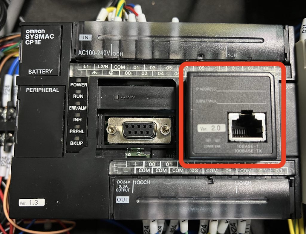
The CP1E series N/NA □□□ CPU unit type requires an Ethernet option board (Model CP1W-CIF41) to connect to the irBoard.
* Note that the N/NA □□ S CPU unit type does not have an Ethernet option board.
Communication Settings
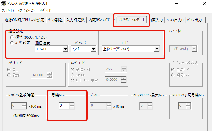
- On the Serial Option Board tab of the PLC system configuration, configure the following settings:
- Check user settings
- Choose 115200 to enhance communication speed.
- Select 7, 2, E in parameters
- Select the upper link (default) in mode.
- Select 0 for station No.
- Once set, transfer the settings to the PLC and then turn the power back on for the PLC.
Network Settings
Network configuration occurs via a web browser.- Connect an Ethernet cable and set it up to connect to a PC.
- The Ethernet option board is 192.168.250.1 right after purchase; adjust the PC's network settings to connect to this address.
- Access http://192.168.250.1/J00.htm using a web browser.
-
When prompted for a password, enter ETHERNET and press the Register button.

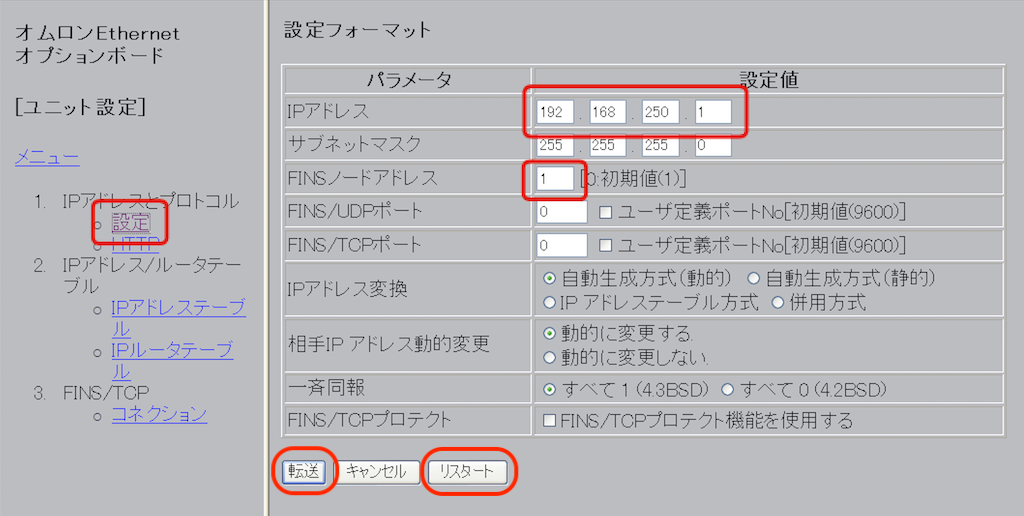
- From the menu on the left side of the page, select Configuration under IP Address and Protocol.
- Set the IP address to your desired address. Set the FINS node address to the end of the IP address (1 in the figure). Apply the subnet mask if necessary.
- After applying the settings, press the Transfer button to update them.
- Press the restart button to update the IP address.
- When accessing with a web browser after configuration, replace the IP address of http://192.168.250.1/J00.htm with the IP address you specified.
Ethernet Initialization of an option board
If you lose the IP address you've set, you can reset it to 192.168.250.1 by initializing the IP address.To begin, follow the steps below.
- Turning on A525.01 initiates the setup process.
- Turn on A525.09 and restart the Ethernet option on the boat.
- After the restart is complete, A525.09 is turned off.
For CJ2M series
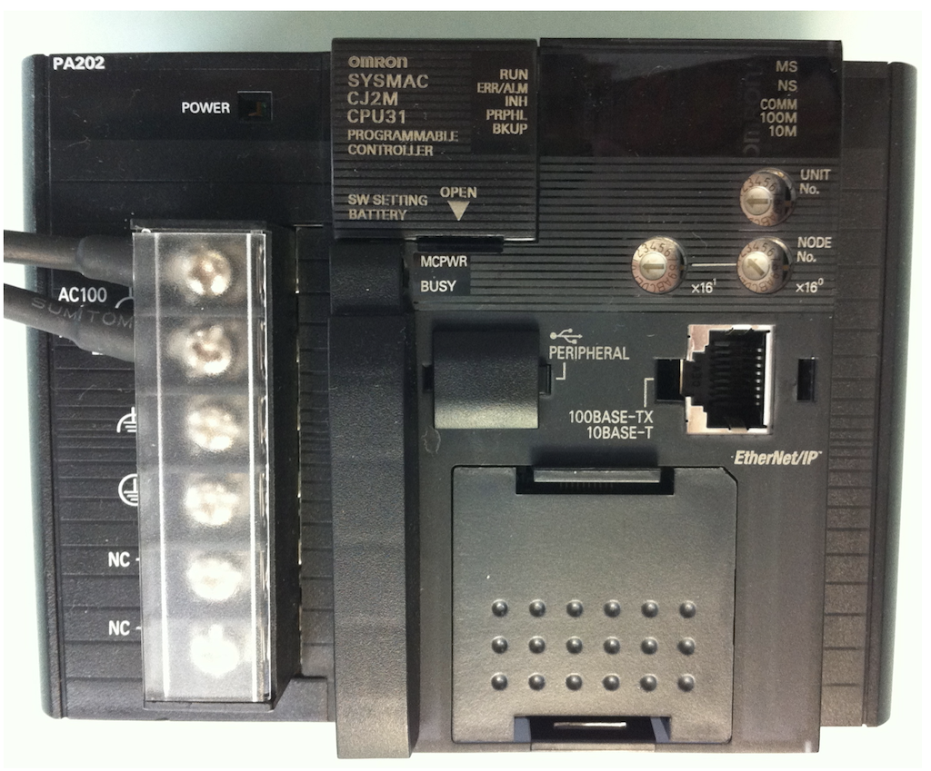
For Ethernet with built-in PLC
(CJ2M CPU31 with IP address 192.168.250.2)
-
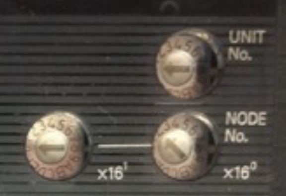
Set the node number of the PLC before turning on the power.
The node number is the last digit of the IP address; for 192.168.250.2, the last digit 2 is the node number. When configuring the node number, convert it to hexadecimal format and set it using the node setting digital switch on the PLC.
- After setting, switch on the power.
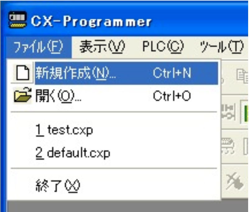
- Open CX Programmer and create a new project.
- Choose the CJ2M as the PLC model.
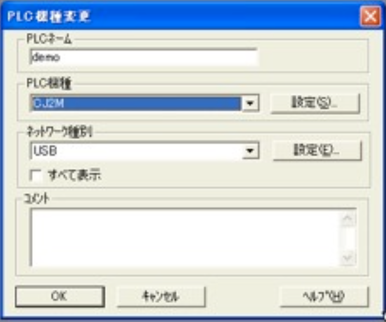
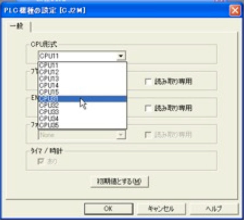
- Press the Set button, select CPU31 in the dialog that appears, and then click the OK button. In the Change PLC Model dialog, click OK again to close it.
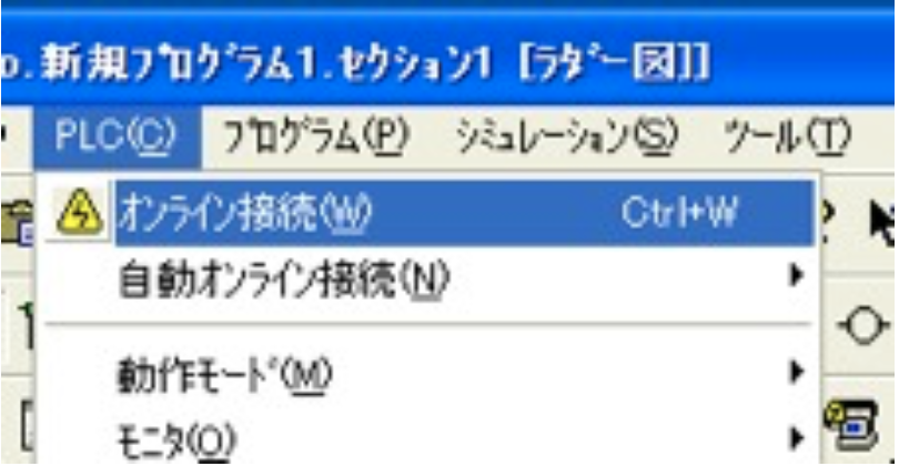
- Next, choose "Online Connection" from the PLC menu to establish a connection with the PLC.
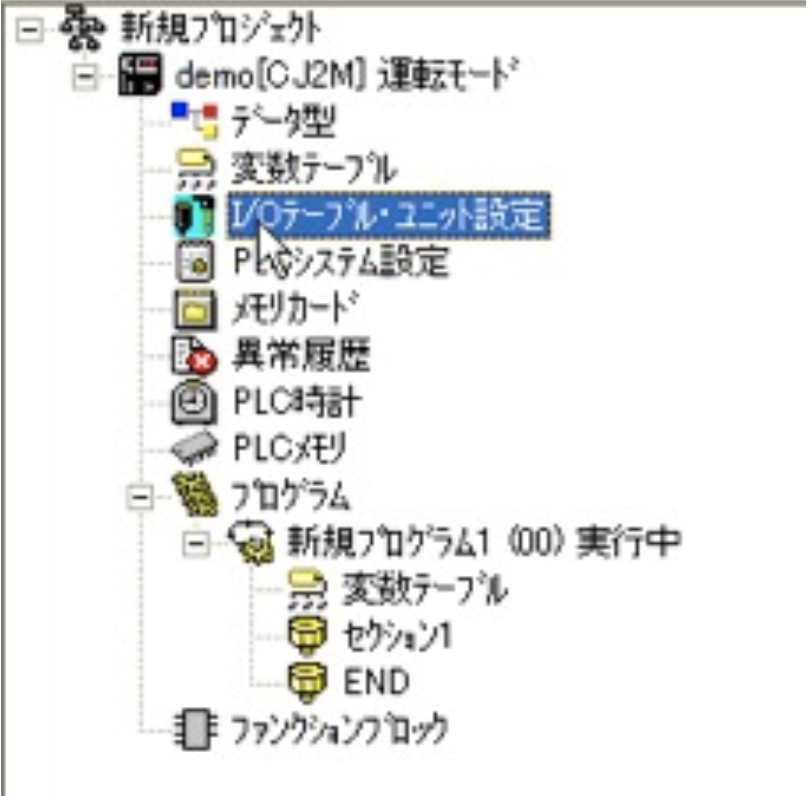
- Open the I/O table unit settings from the list in the tree view on the left.
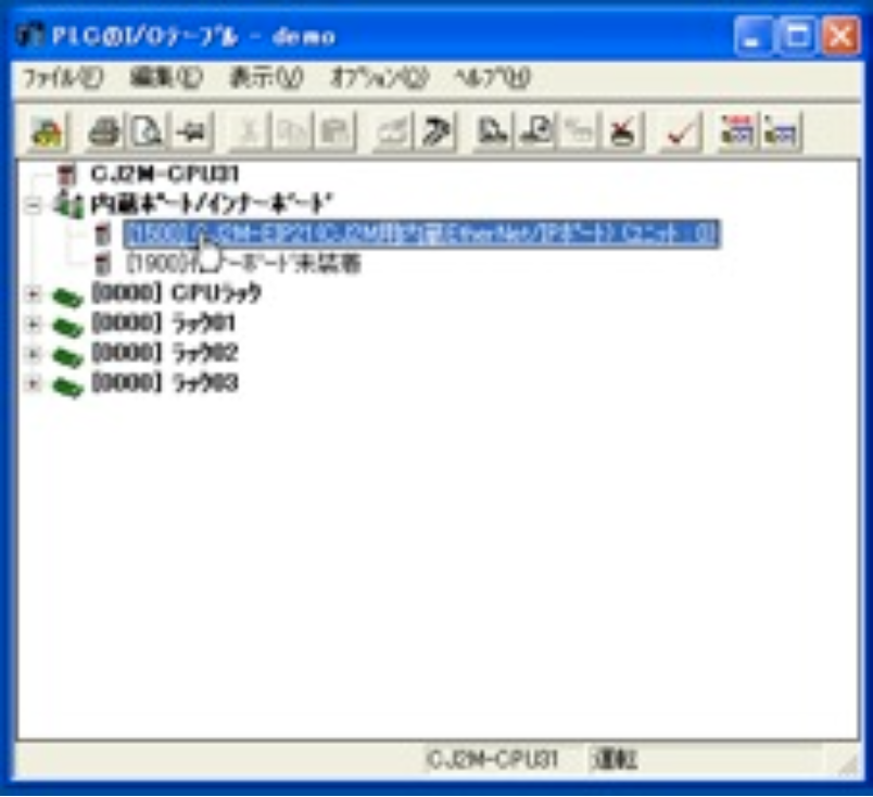
- Open the CJ2M-EIP21 (internal EtherNet/IP port for JC2M) (Unit: 0) on the internal port/inner board.
-
Select the TCP/IP tab, enter 192.168.250.2 as the IP address and 255.255.255.0 as the subnet mask, then click OK to close the dialog box.
When configuring the IP in irBoard, provide the IP address indicated here.
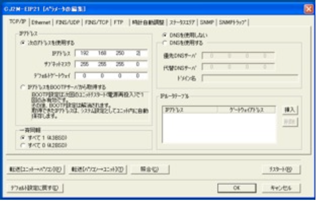
- Select "Transfer [PC->PLC](T)" from the Options menu to send settings to the PLC.
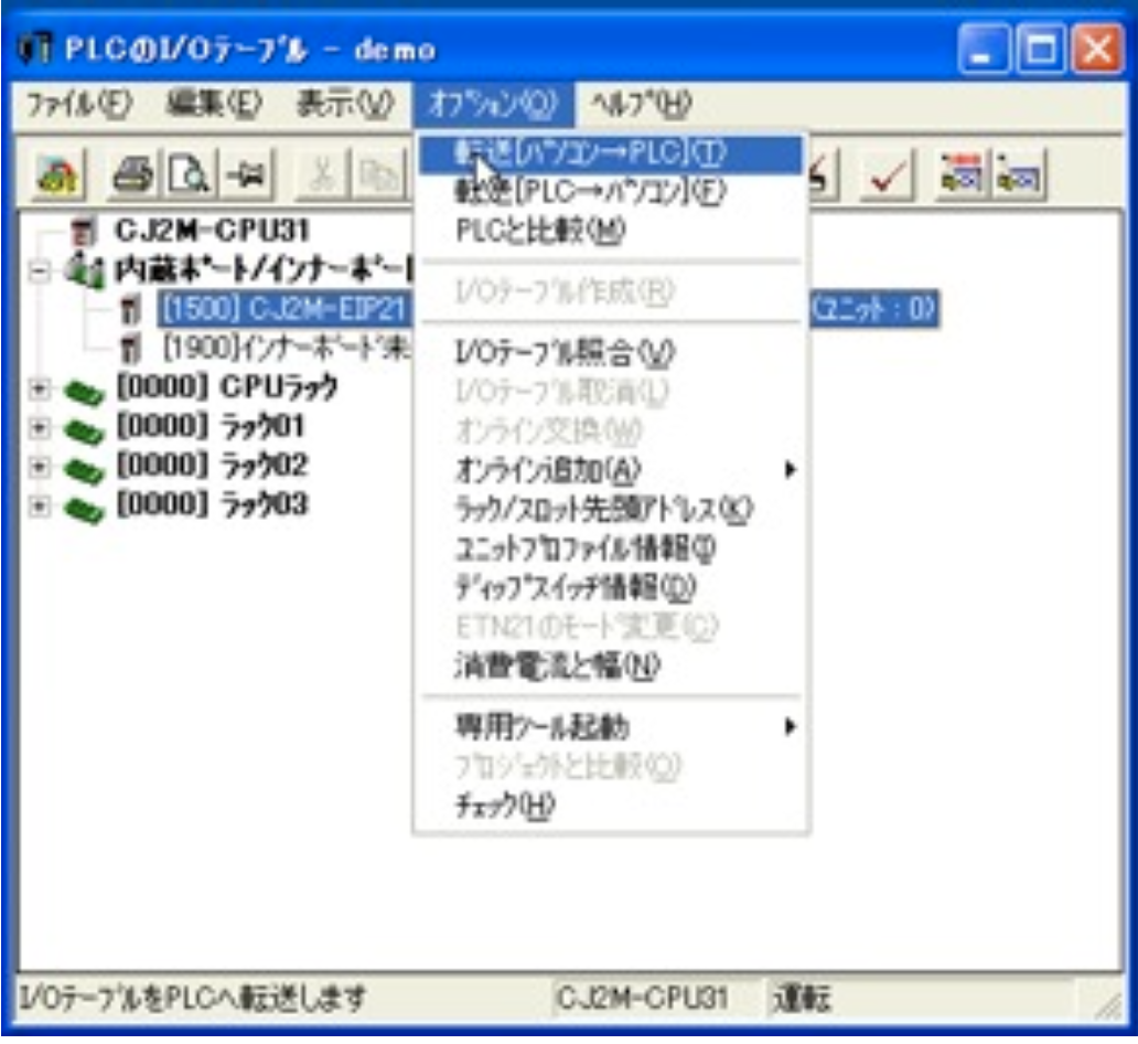
- If you encounter a version mismatch alert during the process, click Yes to proceed with the change.

* We don’t have an English version of some applications. Some screenshots are from the Japanese edition. Please locate a similar screen in your application.